239 Results
View results:
Sort by:

This article describes and explains the influence of bending stiffness of cables on their internal forces. Furthermore, the text provides information on how this influence can be reduced.

The data exchange between RFEM 6 and Allplan can be done using various file formats. This article describes the data exchange of a determined surface reinforcement using the ASF interface. This allows you to display the RFEM reinforcement values as level curves or colored reinforcement images in Allplan.
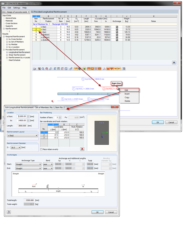
With the introduction of OSG graphics for the representation of design reinforcement in RF‑CONCRETE Members and CONCRETE, you can also select the reinforcement position directly in the graphic. Right-click the mouse to open the context menu where you can edit, copy, or delete the selected reinforcement position.
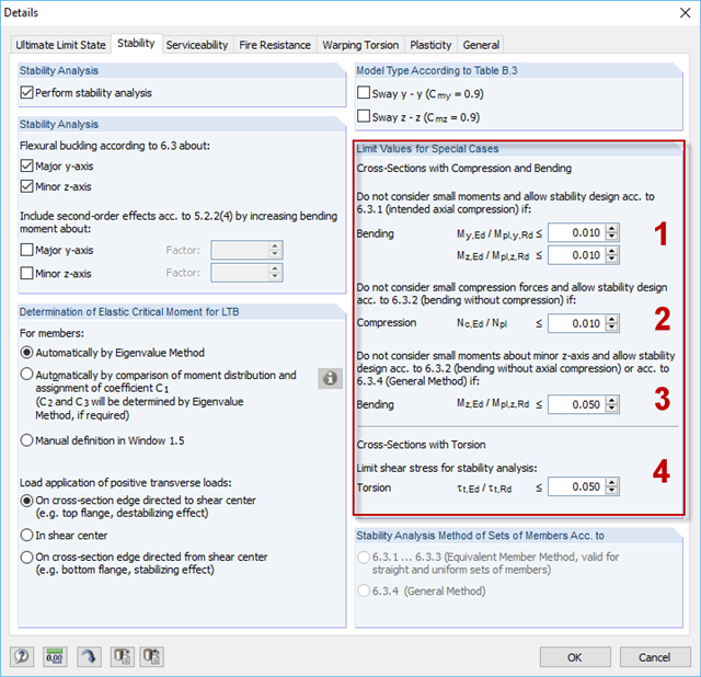
For situations where no design is available, RF-/STEEL EC3 provides the option to neglect the respective internal forces. Examples of such situations are: bending and compression on angle sections, multi-axial bending for the design according to the General Method, torsion.
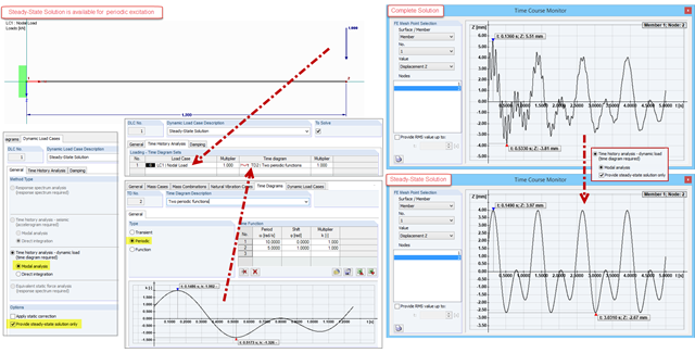
The steady state for periodically excited structures can be determined by means of the modal analysis in the DYNAM Pro – Forced Vibrations add-on module. This is an advantage if only the structure's steady state is of interest. Instead of a complete solution of the equation of motion, only a special solution is displayed.
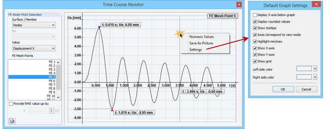
The Time Course Monitor displays the results of a time history analysis from RF‑/DYNAM Pro – Forced Vibrations. The graphic can be adjusted in the settings. This can be reached by right-clicking in the shortcut menu. For example, you can activate or deactivate the grid in the graphic. Those changes are overtaken into the printout report when you print the graphic.
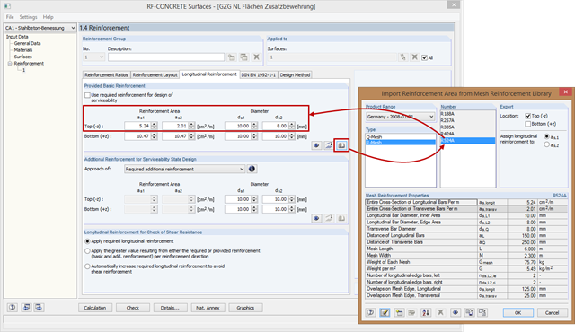
In RF-CONCRETE Surfaces, the reinforcement areas of the mesh reinforcement for basic and additional reinforcement are not entered manually, but you can select them in the library. Therefore, various product ranges are available (for example, from Germany, Austria, and the United States).
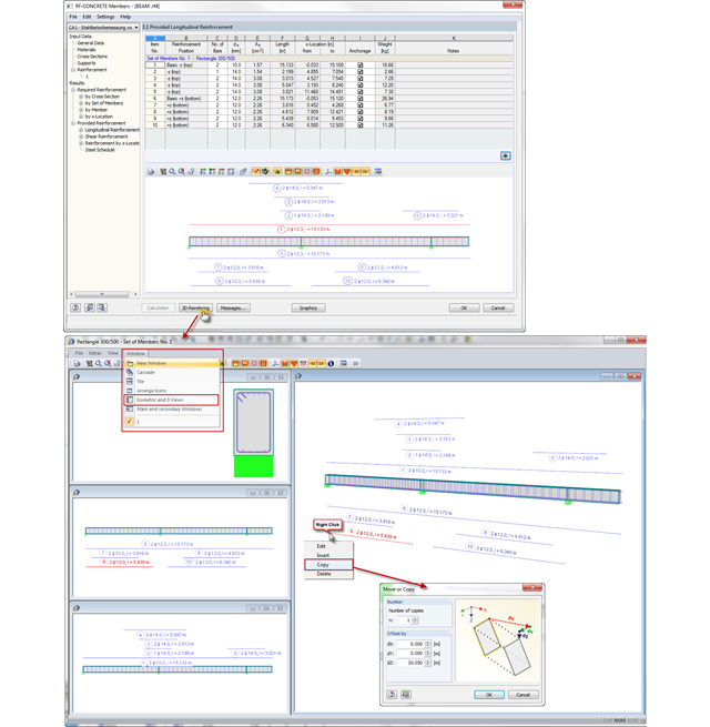
In CONCRETE and RF‑CONCRETE Members, you can open a dialog box with a 3D rendering of the existing reinforcement in Window 3.1 or 3.2. Now, you can also display different reinforcement views in several dialog boxes at the same time. The "Isometric and 3 Views" option known from RFEM is available here as well.
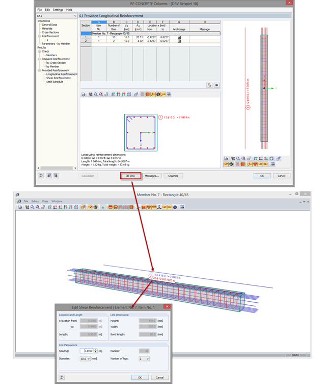
The new options for the graphical display of reinforcements that were implemented in RF‑CONCRETE Members and CONCRETE are now also available in RF‑/CONCRETE Columns.

The Steel Design add-on in RFEM 6 now offers the ability to perform seismic design according to AISC 341-16 and AISC 341-22. Five types of seismic force-resisting systems (SFRS) are currently available.
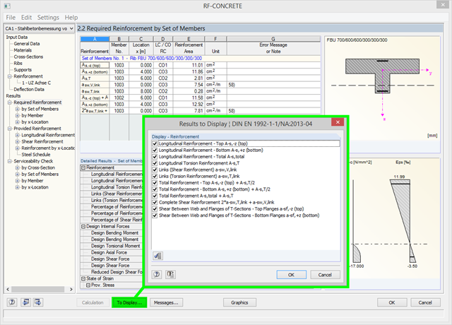
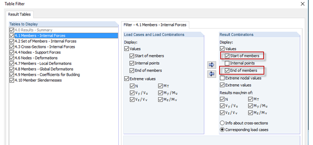
Using the [To Display…] button, you can specify the amount of reinforcement to be displayed in the results of the required reinforcement in Window 2.2 of RF‑CONCRETE and CONCRETE. In addition to the default setting, you can display the resulting reinforcement amount as (for example) the sum of the longitudinal and longitudinal torsion reinforcement, or the sum of the torsion and shear reinforcement. You can also reduce the number of preset results, of course.
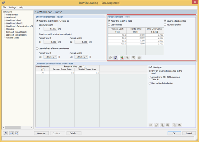
RF-/TOWER load was extended with force coefficients for rounded profiles of four-sided towers and square-edged profiles of three-sided towers. The force coefficients for rounded profiles are determined using the Reynolds number. Previously, you could only use the rounded profiles for four‑sided towers and the square‑edged profiles for three‑sided towers.
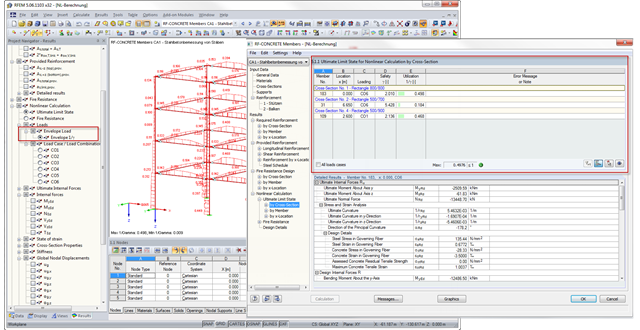
With RFEM 5.6.1103 and RSTAB 8.6.1103, there is an improved result output for the nonlinear calculation of reinforced concrete design in RF‑CONCRETE Members and CONCRETE. The new result windows include tables with a wide range of loading results; for example, governing load with the maximum ratio. In addition, you can now display the envelope results for the maximum ratio graphically.

Using an example of a steel fiber-reinforced concrete slab, this article describes how the use of different integration methods and of a different number of integration points affects the calculation result.
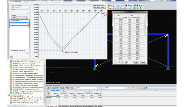
RF-/DYNAM Pro - Forced Vibrations provides the option of a time course monitor. During the evaluation process, you can compare several graphs directly in the program. In addition, you can transfer the figures to the printout report or export them directly to Excel as a value table.
A successful project process involves not only the building owner and the engineer, but also the designers. These days, they also have to design standard connections in steel structures themselves. To do this, the corresponding internal forces of connections are required.
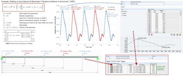
To simulate an excitation that varies over time and changes its position, you can combine several loading time diagrams in RF‑/DYNAM Pro - Forced Vibrations.

The automatic surface reinforcement design process determines a surface reinforcement that covers the required amount of reinforcement.

Various optimizations are available with program version x.06.1103. The RF-/FOUNDATION Pro add-on module has also been subjected to further development.

In order to design longitudinal reinforcement for the serviceability limit state, it is necessary to enable this function. This is possible in Window 1.1 General Data under the "Serviceability Limit State" tab. After you select the "Analytical..." method of checking, you can select the corresponding additional options in the section for determining the longitudinal reinforcement of the "Settings of Analytical Method of Serviceability Limit State Design" window.